
Kévin Juge
- Continuous improvement
- Green Belt - Lean Six Sigma
- Project management support
- Energy efficiency
Electronic prototyping board
This project was carried out in 2014/2015
Objectives:
- Refresh my knowledge in connection with the computer science courses taken 8 years earlier in IUT
- Preparing future projects (modeling at this time)
Hardware
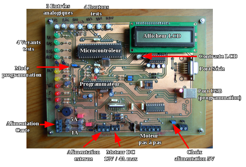
- Power supply circuit with regulator (to be able to use an external 12V power supply or a USB power supply)
- A circuit derived from the programmer UsbPicProg, comprising:
- 1 Microchip PIC18F2450 microcontroller (to program the second one)
- 1 charge pump to generate the programming voltage from the 5V coming from the USB port
- The prototyping circuit
- Microchip PIC 16F877A Microcontroller
- Microchip 24C16 memory
- RS232 serial link (Maxim MAX232)
- Buzzer
- 2x16 character LCD display
- ULN2003 drivers to drive a stepper motor
- 4 buttons
- 3 potentiometers (analog inputs)
- 4 LEDs
- H-bridge L298 to control a motor (2 directions, activation and current measurement)
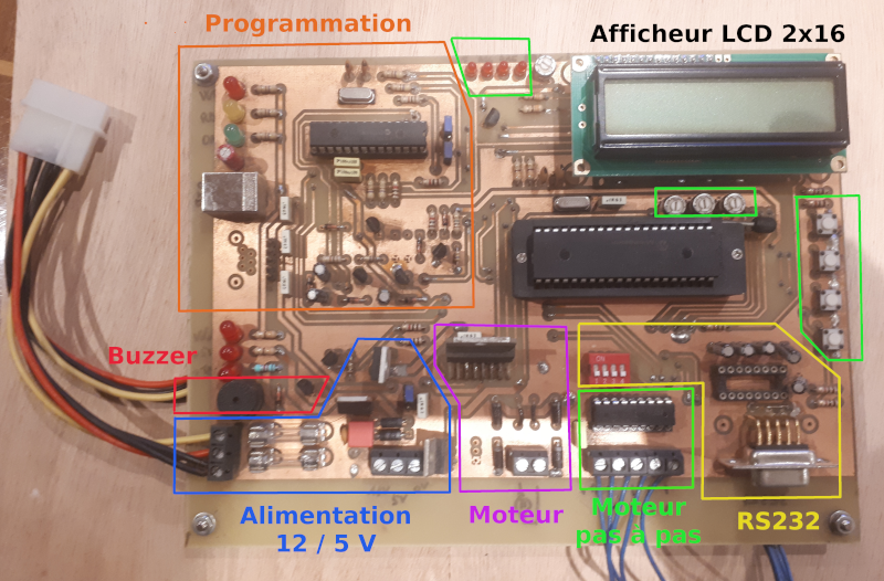
In 2017, a second version of the map was released to improve:
- Use of the serial link of the PIC18F2550 micro-controller in order to use it as a serial / USB converter, which would have required modifying its program afterwards.
- Incorporation of zero insertion force (ZIF) socket to simplify microcontroller change (e.g. PIC 18F)
- 12V power supply management by transistors (buzzer power supply and motors)
First version
Second version
Software
Programming could be done with:
- Open Source software: Code::Blocks and the Small Device C Compiler (SDCC)
- The founder's integrated development environment: MPLAB and the free compiler CC5X (PIC 16F) or CC8E (PIC 18F), which we used in IUT
The programmer program is provided by UsbPicProg
The one developed for the second micro-controller made it possible to test the various functions of the board
Interrupt handling
- Timer (stepper motor control, LEDs, buzzer, ...)
- Serial communication
One of the buttons allows you to select a mode, which is displayed on the LCD display:
- Display of analog input values on the LCD display
- Management of a motor using the Pulse Width Modulation (PWM) chopper, display of current, voltage, and direction of rotation
- Management of a stepper motor, display of the direction of rotation
- Buzzer management, variable frequency thanks to PWM
- Communication via serial link
Self-guided vehicle
This project started in 2016
Objectives:
- Improve a radio-controlled vehicle, towards a digital control, to then make it self-guided using a camera, and add a graphical interface
This project was carried out in several parts
- Design and production of electronic cards for the vehicle and the remote control
- Development of microcontroller programs in C
- Development of communication, image processing and graphical interface programs in C/C++, Qt and OpenCV
Vehicle and remote control
Hardware
Electronic board of the remote control:
- 9V / 5V power supply from a battery
- 2 analog potentiometer controls for propulsion and steering
- Added 4 buttons: 4WD, horn, headlights and auto-guidance
This one is composed of:
- PIC 16F1508 Microcontroller
- 433MHz radio transmitter
Electronic card of the vehicle:
- 7.2V / 5V power supply by 3000mAh NiMh battery
- L293D H-bridge steering servo motor regulation
- Horn by buzzer
- Propulsion regulation by H bridge L298: control of the 2 motors and current measurement
- PIC 16F886 microcontroller
- Headlights
- External power supply management for Raspberry
- I2C communication with the Raspberry
- 433 MHz radio receiver
In 2017, a second version of the map was released to solve some problems:
- Replacement of the L298 H bridge by 2 MC33887 H bridges on a daughterboard due to the space available, in order to increase the motor current from 2 to 5A and manage bridge faults
- Improved card and external power management
- Separation of outputs for lights (left, right and rear)
Software
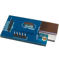
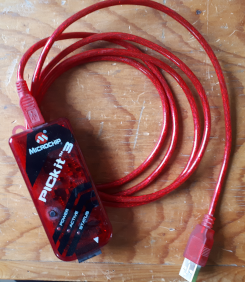
At the beginning of the project I used Code::Blocks, the Small Device C Compiler (SDCC) and the UsbPicProg programming card for programming microcontrollers Then I acquired a PicKit3 programmer/debugger, used with MPLABX (Linux compatible) to simplify debugging.
UsbPicProg
PicKit3
Remote control features
Send a frame every 10 ms, containing:
- Propulsion setpoint
- Direction setpoint
- Position of buttons
Vehicle Features
- Vehicle stop by watchod timer (in case of loss of communication)
- Stop the motors when the battery is discharged
- Control by I2C (Raspberry or human-machine interface)
- Control by serial link (remote control)
- Management of chopper faults to enable motor control
- Adjusting the center steering position
- Propulsion and steering regulation by PID regulator (Proportional, Integral, Derivative). Position measurement for steering would require a more accurate amplifier or converter
- Activation of the 2 choppers (4 wheel drive) when the mode is activated or when the current of the first motor is above a threshold. In use, the 2 choppers must be activated, otherwise the unused engine-transmission torque brakes the vehicle
- Horn management
- Reset of commands from the remote control every 15 ms
- Motor current measurement
- Battery voltage measurement
| I2C emission (status) | I2C reception (commands) |
|---|---|
| Propulsion reference | Propulsion reference |
| Direction reference | Direction reference |
| Steering position | Steering adjustment |
| Maximum left position | Command word |
| Maximum right position | |
| Forward motor current | |
| Rear motor current | |
| Battery voltage | |
| Nominal battery voltage | |
| Minimum battery voltage | |
| Command word | |
| Status word |
Communication, image processing and graphical interface
Raspberry
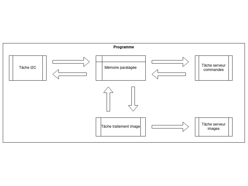
This program, in its first version, was written in C, and made it possible to transmit data between the vehicle and a remote computer thanks to the I2C and Wifi of the Raspberry
Since its creation several improvements have been made:
- Modification of data transfer in the program: use of message queue instead of shared memory and mutex, following professional experience
- Modification of "server" tasks:
- Data and image separation: 2 sockets on 2 threads
- Testing different protocols: TCP, UDP, RTP (suitable for video streams)
- Image compression before transmission
In connection with the restricted documentation of OpenCV in C language, this program evolved towards Python then C++, more powerful and adapted to low-level management (bit fields).
First version with separate servers
Latest version with message queue
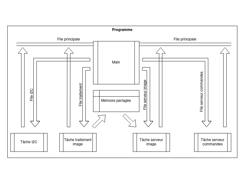
Each task sends its messages to a main queue The main program forwards the message to the correct recipient
The image processing task transmits the last image to the shared memory, then the image server task transmits it to the remote computer
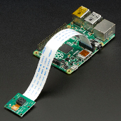
Raspberry + camera
ESP32 microcontroller
Due to the high energy consumption of the Raspberry, in 2021 I turned to an ESP32 microcontroller associated with a camera. The ESP323-CAM module is thus composed of this one, an external memory of 4 MB, a connector for the camera and its Wifi antenna 2 cameras were offered and this wide angle is better suited for this application
As the resources of this micro-controller are limited, image processing in particular, I simplified the program in order to transmit the data between the vehicle and the remote computer, as well as send the images.
The ESP32 can be programmed with the Arduino Integrated Development Environment (IDE) or the IoT Development Framework (IDF) compatible with VsCode and Eclipse. Being more experienced in C/C++, I use this framework with Eclipse.
The main program takes care of the initialization of Wifi and buffers The I2C task communicates with the data server thanks to 2 circular buffers The task linked to the camera receives the parameters of the camera from the image server thanks to a circular buffer and returns the last image to it (buffer of 3 images linked to the capture)
Architecture with circular buffers
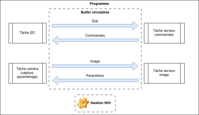
ESP32-CAM
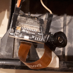
Human-machine interface
This program is written in C++/Qt
- Interface containing the different functions described above
- Controls: horn, headlights, manual steering, autonomous steering, image display, steering adjustment, data display in graphic form
- Status information of effective commands: commands are sent to the vehicle and then returned in the status word
- 2 tasks related to transmission / reception of data and reception of the image
Using ESP32 introduced changes:
- Addition of a task related to image processing with OpenCV
- Added camera configuration (image size, filters)
- Addition of images related to image processing: color space modification, line detection, line representing the direction, ...
Interface with image from the camera
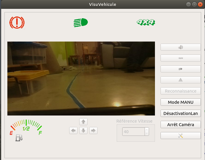
Image processing
Image processing is done using the OpenCV library and allows the vehicle to follow a colored line
The steering angle of the vehicle is taken from the detection of this line, carried out as below:
- White balance correction
- Changing RGB to HSV color space (hue, saturation, color)
- Detection of line edges from a tint
- Filtering of the bottom 1/3 of the image, close to the vehicle
- Line segment detection
- Removal of horizontal segments
- Calculation of the direction of the left and right segments
- Average directions
- Steering angle calculation
- Display of a bar centered at the bottom of the image to represent the direction instruction
After using ESP32, intermediate images can be displayed on the GUI, which simplifies debugging
Difficulties and improvements
- Latency on vehicle commands (propulsion, steering) from the GUI
- Lack of precision for the steering position
- Latency for image transfer and high CPU usage of the Raspberry: it would be better to compress the images with its hardware encoder
- Line detection is more complex the faster the vehicle is moving. Indeed, the different steps: communication, latency problem, processing (including reflections related to lighting, very resource-consuming), sending commands take time
I was thinking of integrating other more complex functions
- Guidance thanks to machine learning: detection of direction signs (turn, turn around or read a text)
- Realization of the plan of an apartment: the vehicle moves alone and establishes a plan, which brings up the problem of calculating distance without reference
Storage radiator
Radiator
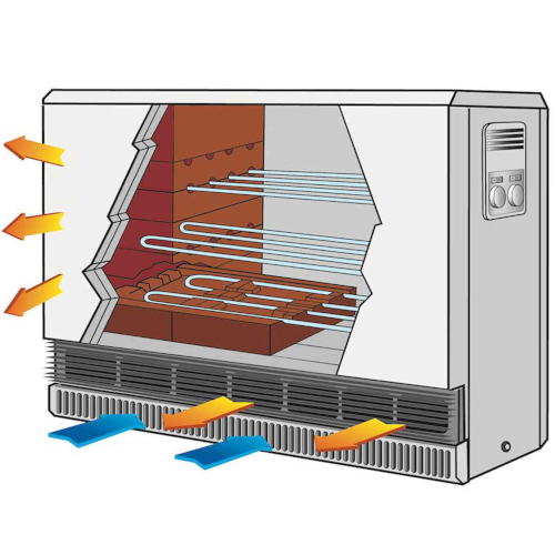
Old electronic card
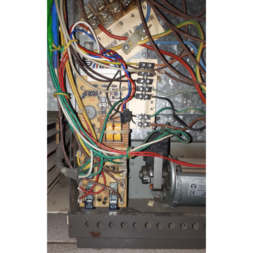
This project began in the fall of 2021, linked to the obsolescence of an electric storage radiator (with 300kg of bricks, which allows 48kWh to be stored)
Goals:
- Remedy the obsolescence of spare parts, including the charge regulation card
- Add functionalities as for current connected thermostats (room temperature regulation, time scheduling, configuration, as well as fault management and trend display using a web interface)
Hardware
Creation of an electronic card for electronic load regulation
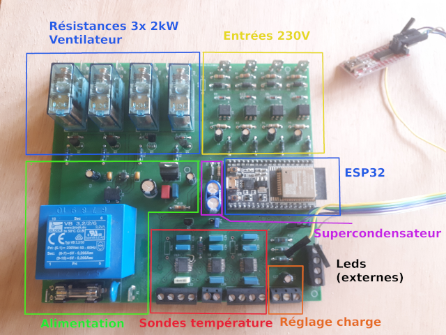
Power circuit
- 230V AC / 9V DC power supply
- 9V DC power supply : relay control
- 5V DC power supply : super capacitor, logic inputs and micro-controller
- 3,3V DC power supply : MAX31865 converters, load adjustment and LEDs
Logic inputs
- Off-peak hours (230V)
- Load restart (230V)
- External thermostat (230V)
- Fan safety (230V)
- Power supply presence (3,3V) - Input (in the RTC power domain) for putting the microcontroller into standby and waking up
Analog inputs
- 3 temperature probes / converter - SPI
- Core probe – Pt700
- Outdoor probe – Pt100
- Room sensor – Pt100
- 1 analog input: load level adjustment
Logic outputs
- 3 16A relays for the resistors (2kW)
- 1 16A relay for fans
Super capacitor
- Allows you to replace a battery and is used to power the micro-controller in the event of a power outage (in order to save the parameters and timestamp)
Micro-controller
- ESP32-WROOM-32D on ESP32-DevKitC development board
Due to the use of Max31865 temperature converters, which are only manufactured in SMT, I chose to have the card manufactured after a first test with my engraving machine. Which explains the size of the tracks, vias and other through components.
In 2023: Production of a second version to correct some errors
- The ESP32-DevKitC-32D development board is obsolete: replaced with an ESP32-WROOM-32E Module, which allows the removal of the 5V DC power supply and voltage regulators
- Correction of an inversion between the power presence signal (non-RTC input) and the second LED (not configurable at output)
- Addition of pull-up resistors for the SPI connection of the probe converters
- Addition of an entry for decoding the Pulsadis EDF signal (information related to pricing)
Software
The ESP32 module includes
- 2,4GHz Wifi module + Bluetooth + Bluetooth LE
- flash memory
- a Wifi antenna (onboard)
- the microcontroller can be clocked up to 240MHz and includes 2 cores
- it is equipped with FreeRTOS
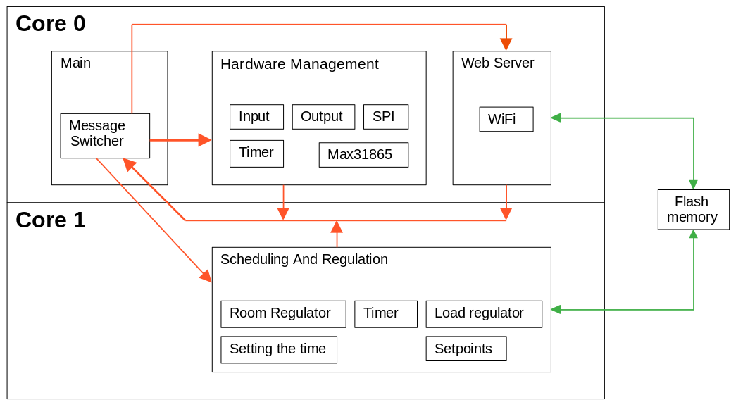
The software is made in C++ with 4 main classes, including the different tasks
Initial organization of tasks
Class diagram
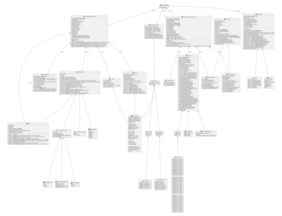
The classes
Main
Application entry point
Initializes the main classes (MessageSwitcher, HardwareManagement, WebServer, SchedulingAndRegulation), starts their tasks and infinitely calls the “switchMessage” function.
Main classes (containing the different tasks)

Main program activity diagram
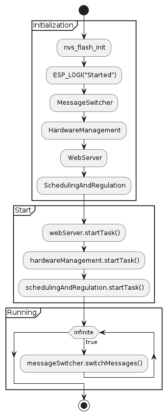
MessageSwitcher
Class dedicated to message queues
The “switchMessages” function routes incoming messages to the appropriate message queues (based on the message ID)
Activity diagram "switchMessages"
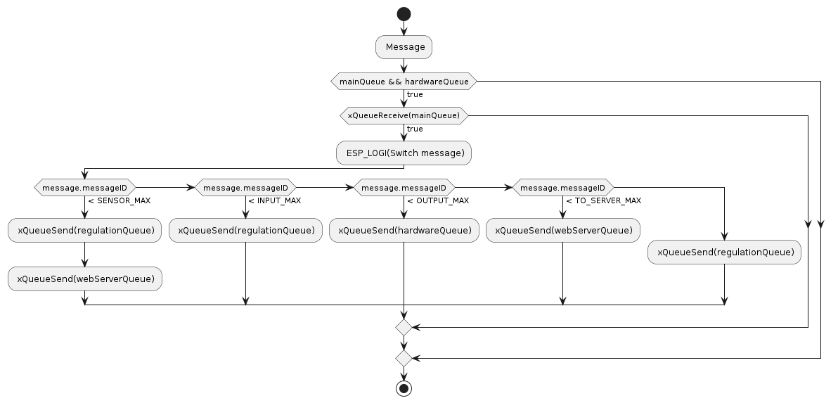
HardwareManagement
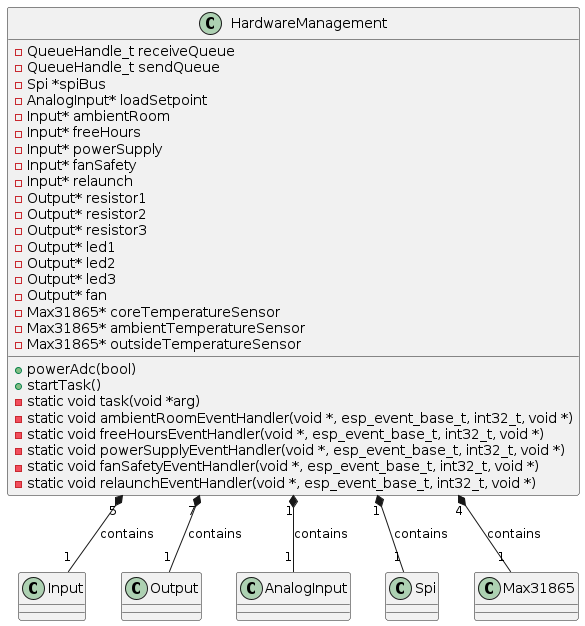
Management of hardware/software interfaces
- 1 Timer (1s) to trigger the measurement of analog values
- 1 SPI bus: shared between the 3 temperature probe converters
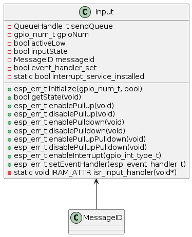
- 5 logic inputs with their interrupt handler: which sends a message to an event handler or a message queue in the event of a change of state
- 1 analog input
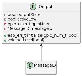
- 7 logic outputs: LEDs and relays
- 4 filters to use an average value of analog measurements
The execution of the task allows, successively
- Reading messages received in the message queue
- Update, if necessary, the status of the outputs
- Successive reading, if authorized, of analog measurements and sending, if necessary, of new values in the message queue
The state of the inputs is updated by interrupt: a message is sent to the message queue upon a change of state
A timer is used to trigger the measurement of analog values, due to their low frequency (1s)
HardwareManagement class
Input class
Output class
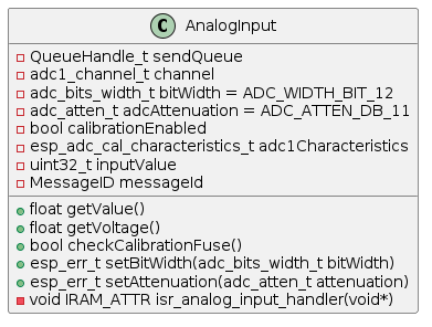
AnalogInput class
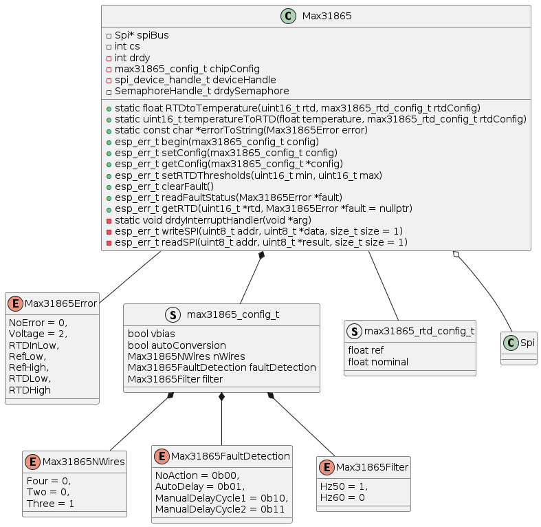
MAX31865 class
SPI class
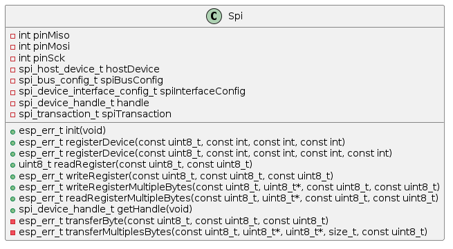
The code for Max31865 and SPI comes from the following GitHub repository:
SchedulingAndRegulation
Management of regulators (load and ambient temperature), loading/saving of parameters
- 1 Timer (1s) to transmit trends to the web server
The execution of the task allows, successively :
- Reading messages received in the message queue
- Updating, if necessary, data linked to regulators, input status, saving parameters and putting them on standby, setting the time and updating parameters
- Updating set points based on hourly planning
- Regulator update
- Update of relay and LED control
Setting the time
The RTC clock is that of the microcontroller, however it stops in deep sleep. Setting the time, and not the date, is done autonomously using the off-peak/peak hours information and the web interface allows the user to set the timestamp.
In the location where the device is installed, off-peak hours are triggered according to 2 slots per day 3 p.m.-5 p.m. and 10 p.m.-6 a.m.
Pricing periods

If the off-peak period lasts 2, it is 5 p.m. Otherwise it’s 6 a.m. the next day.
SchedulingAndRegulation class

Regulator class
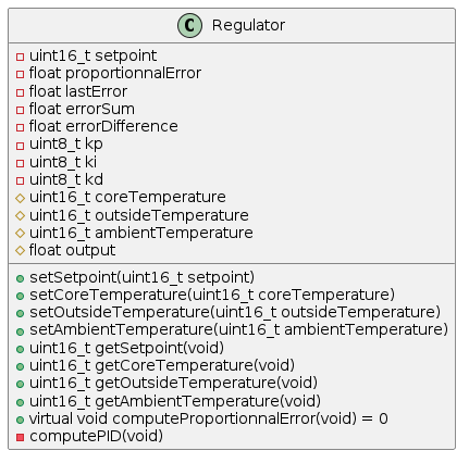
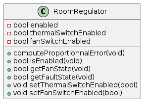
RoomRegulator class
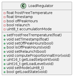
LoadRegulator class
This page allowed me to improve the algorithm of my PID regulator:
This page allowed me to implement the charge regulator, and to add some features such as the shift of the charge point:
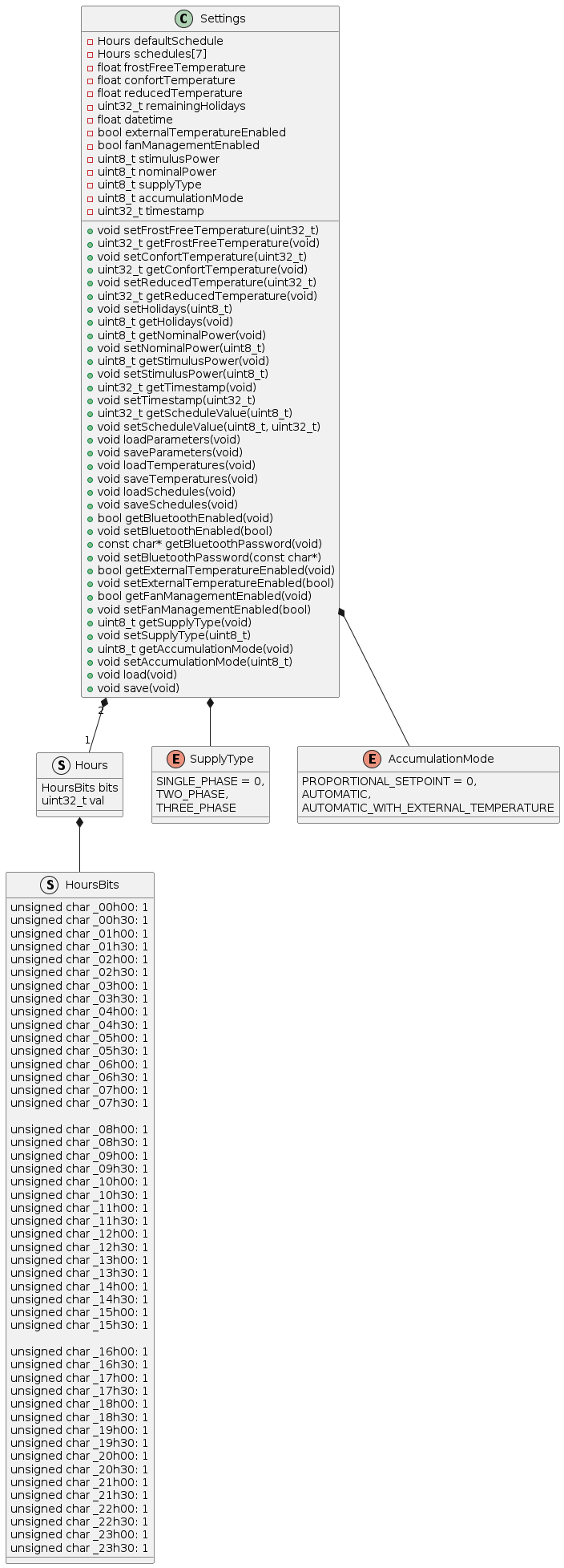
Settings
They contain :
- 1 default schedule, i.e. 24 hours configurable by 1/2 hour
- 1 weekly schedule (7 days, configurable per 1/2 hour)
- frost-free temperature
- comfort temperature
- reduced temperature
- number of vacation days remaining
- timestamp
- activation of the external temperature probe
- activation of fan management
- restart power
- nominal power
- type of power supply (single-phase, three-phase)
- type of accumulation (proportional, automatic, etc.)
- load shift (beginning, middle, end of night)
To simplify the program, each of the WebServer and SchedulingAndRegulation tasks instantiates the Settings class, which allows you to load/save settings from flash memory. When a modification of a parameter has been made from the web interface, it is saved in the flash and a signal is sent to the SchedulingAndRegulation task to indicate that a modification has taken place. Three message identifiers, corresponding to the different parameters, are implemented: parameters, instructions and scheduling.
Settings class
WebServer
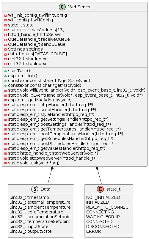
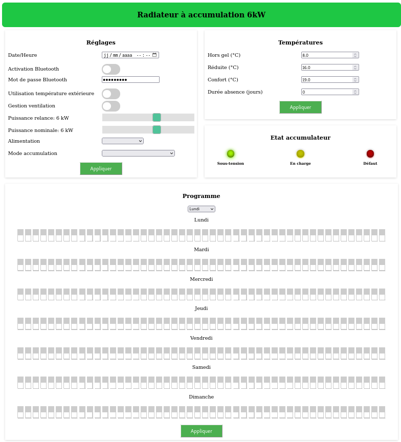
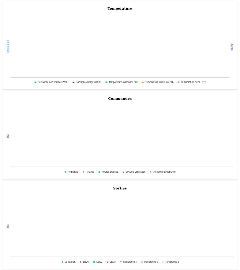
Management of WiFi initialization in access point, management of connections and exchange of data with the web page (including configuration) using several resource managers and a Json library (cJSON).
The website is created in HTML/CSS, and all files are stored on the microcontroller due to the access point configuration, which requires a lot of memory (79.5kb).
The execution of the task allows, successively:
- Reading messages received in the message queue
- Copy, if necessary, data linked to trends into a rotating buffer
- Updating indexes linked to the buffer
WebServer class
Web page (top)
Web page (bottom)
Solar heating
This project began during the summer of 2022
Goals:
- Optimizing energy recovery from a solar thermal system
- Automate the emptying and filling of the circuit according to climatic conditions (frost)
- Read data using remote cards, in order to limit cables (temperature, irradiation, etc.)
- Dialog with a boiler to read its values (temperatures, etc.) and possibly control it
- Be able to subsequently integrate a solar tracking system in order to optimize the inclination of the panels
- Generate trends on a web interface (temperatures, recovered power, etc.)
- Anticipate future developments (additional inputs/outputs)
Hardware
Electronic boards
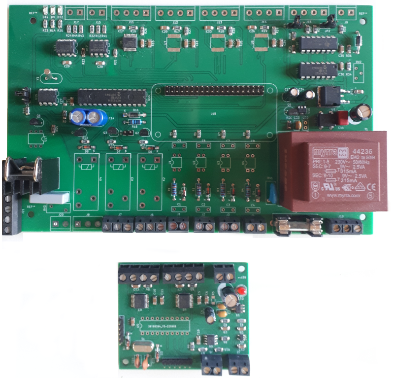
Main card
Power circuit
- 230V AC / 12V DC power supply
- 12V DC power supply : relay control
- 5V DC power supply : super capacitor, RTC clock, analog outputs, and Raspberry Pi Zero W (or ESP32)
- 3,3V DC power supply : MAX31865 converters, logic inputs, communication
Logic inputs
- Low tank level (230V)
- High tank level (230V)
- Reserved (230V)
- Reserved (230V)
- Power supply presence (3,3V) - For putting the nano computer into standby and waking up
Analog inputs
- 4 temperature probes / converter - SPI
- Temperature go panel – Pt100
- Temperature return panel – Pt100
- Low exchanger temperature – Pt100
- High exchanger temperature – Pt100
Logic outputs
- 1 16A relays for drain solenoid valve
- 2 16A relays in reserve
Analog outputs
- 2 analog outputs (to 10V) with MCP4922 / amplifiers (SPI)
- circulator with Triac (230V / 16A)
Communication
- 1 tranceiver RS485 for external card communication
- 1 tranceiver RS485 for boiler communication
Super capacitor
- Allows you to replace a battery and is used to power the nano computer in the event of a power outage
RTC clock
- DS1337 (I2C)
Nano computer
- Raspberry Pi Zero W
Deported card
Power circuit
- 9V DC power supply
- 3,3V DC power supply : MAX31865 converters, inputs, communication, and micro-controller
Analog inputs
- 2 temperature probes / converter - SPI
- Temperature go panel – Pt100
- Temperature return panel – Pt100
- Solar irradition
- Pressure, température, humidity - BME280 (SPI)
Communication
- 1 tranceiver RS485 for main card communication
Micro-controller
- Microchip PIC16LF1508
Wind turbine
This project started in 2023
Goals:
- Create a wind turbine prototype based on a kitesurfing wing
- Test viability
Hardware
The system will be made up of several electronic cards, adapted to the different parts. And different configurations will be tested.
- The instrumentation cards, positioned on the wing. This allows information linked to its dynamics (gyroscope / accelerometer) to be reported. Radio communication is necessary due to the length of the lines, and 2 configurations will be tested: Bluetooth and sub-GHz radio
- The control card, which collects, processes the information and controls the wing. This card is compatible with both radio communication modes.
- Power cards which adapt the voltages necessary for the servomotors
- The fan control card, which is optional, and will allow the system to be tested
Instrumentation board 1 (on the wing)
First option of the card where the micro-controller interfaces between the sensors and the radio transmitter
Power circuit
- Battery powered up to 9V DC
- 3.3V DC power supply: gyroscope, accelerometer, radio transmitter, micro-controller
Sensors
- IIS2DLPC accelerometer
- IAM-20380 Gyroscope
Communication
- Si4060
Micro-controller
- STM8L101F3P
Instrumentation board 2 (on the wing)
Second option of the card where it seems possible to use the BlueNRG-M2SP module as an interface with the sensors and transmitter, due to its programming possibilities.
Power circuit
- Battery powered up to 9V DC
- 3.3V DC power supply: gyroscope, accelerometer, BlueNRG-M2SP
Sensors
- IIS2DLPC accelerometer
- IAM-20380 Gyroscope
Communication
- BlueNRG-M2SP
Order card
Power circuit
- 12V DC power supply (from a remote power supply due to the power required to control the wing)
- 3.3V DC power supply: supercapacitor, analog-digital converter, radio receiver, micro-controller
- 5V / 3.3V DC power supply: USB port
Logic inputs
- Zero crossing of the sinusoidal voltage (230V)
Analog inputs
- Analog-to-digital converter (SPI)
- output voltage of the 3 choppers
- current of the 3 choppers
- Wind speed (anemometer)
- Wind direction (Weather vane)
Analog outputs
- PWM output to adjust the voltage of the 3 choppers
- PWM output for the left rear servomotor
- PWM output for the front servomotor
- PWM output for the right rear servomotor
- PWM output to control the fan (test function)
Communication
- Si4362
- STM32WB55
- Connector for SPI communication (if upgrade required)
Micro-controller
- STM32WB55
Power card
Not knowing the traction force required to control the wing, I plan to use 35kg servomotors. This allows the choppers to be dimensioned.
Features
- 12V DC power supply from a remote power supply due to the power required
- Output up to 12V DC - 6A
- Amplification circuit for controlling the transistor (3.3V / 12V)
- Measuring output voltage and current
- Generic card for the 3 choppers
Fan control board (system test)
Fan control circuit, to simulate wind and test the system
Features
- Fan control by PWM from the control card and Triac (230V AC - 16A)
- Detection of the zero crossing of the sinusoidal voltage (inductive voltage) to the micro-controller
 French